- sjoerdvan / Wemos D1 mini pro.md
- Saved searches
- Use saved searches to filter your results more quickly
- pandalanax/wemos-d1-mini-micropython
- Name already in use
- Sign In Required
- Launching GitHub Desktop
- Launching GitHub Desktop
- Launching Xcode
- Launching Visual Studio Code
- Latest commit
- Git stats
- Files
- README.md
- Advanced
- Analog to Digital Converter
- Communication Protocols
- Neopixels
- Temperature and Humidity
- LED Matrix and 7-segment Displays
- TFT LCD Display
sjoerdvan / Wemos D1 mini pro.md
Download the latest esp8266 micropython binary.
After driver installation do: »’bash sudo kextload /Library/Extensions/SiLabsUSBDriver.kext »’ Then in security settings on your mac, click allow for the kext (kernel extension) to be activated. I needed this for OS X High Sierra
Optional: Erase the flash of the Wemos D1 with esptool
esptool.py -p /dev/tty.SLAB_USBtoUART erase_flash
Run to install micropython on the Wemos D1 with esptool(install this with pip install esptool):
esptool.py -p /dev/tty.SLAB_USBtoUART write_flash -fm dio -fs 4MB 0 ~/Downloads/esp8266-20171101-v1.9.3.bin Notice, use 4MB even though the D1 mini pro has more space. I tried 16MB and it failed.
To connect use screen or picocom (when still connected to usb, restart probably required after driver install)
picocom /dev/tty.SLAB_USBtoUART -b115200
Configure remote access via Webrepl (useful for file transfer f/e)
Connect to the device (see above) and run
Follow the steps (enable and set a password) and you’re done. You can now connect to it via a webinterface (details or use the online (but local browser running) webrepl)
import network sta_if = network.WLAN(network.STA_IF) ap_if = network.WLAN(network.AP_IF) sta_if.active() False ap_if.active() True ap_if.ifconfig() ('192.168.4.1', '255.255.255.0', '192.168.4.1', '8.8.8.8')
Configure your own netwerk:
sta_if.active(True) sta_if.connect('', '') sta_if.isconnected() sta_if.ifconfig()
Or put the following in your boot.py(or main.py) so it connects on boot
def do_connect(): import network sta_if = network.WLAN(network.STA_IF) if not sta_if.isconnected(): print('connecting to network. ') sta_if.active(True) sta_if.connect('', '') while not sta_if.isconnected(): pass print('network config:', sta_if.ifconfig()) connect()
There are two files that are treated specially by the ESP8266 when it starts up: boot.py and main.py. The boot.py script is executed first (if it exists) and then once it completes the main.py script is executed. You can create these files yourself and populate them with the code that you want to run when the device starts up.
Connect via a webinterface which can also send and retrieve files
Activate Webrepl on the device, instructions
Download the webrepl client and open webrepl.html
About time stuff on Micropython
So. micropython doesn’t use the epoch as it should, but utime.time() shows the seconds since 1-1-2000.
Also the clock seems to drift, so using it every 7,5 hours or using settime is a must. Details
Updating the Wemos D1 mini pro to 16mb flash (128M bit)
I used the instructions (and files) from here Make sure you have esptool later than 2.3.1 (I used 2.5.1)
Saved searches
Use saved searches to filter your results more quickly
You signed in with another tab or window. Reload to refresh your session. You signed out in another tab or window. Reload to refresh your session. You switched accounts on another tab or window. Reload to refresh your session.
A tutorial / cheatsheet / how to on micropython
pandalanax/wemos-d1-mini-micropython
This commit does not belong to any branch on this repository, and may belong to a fork outside of the repository.
Name already in use
A tag already exists with the provided branch name. Many Git commands accept both tag and branch names, so creating this branch may cause unexpected behavior. Are you sure you want to create this branch?
Sign In Required
Please sign in to use Codespaces.
Launching GitHub Desktop
If nothing happens, download GitHub Desktop and try again.
Launching GitHub Desktop
If nothing happens, download GitHub Desktop and try again.
Launching Xcode
If nothing happens, download Xcode and try again.
Launching Visual Studio Code
Your codespace will open once ready.
There was a problem preparing your codespace, please try again.
Latest commit
Git stats
Files
Failed to load latest commit information.
README.md
A quick tutorial on how to work with micropython as i found it puzzling in the beginning.
- Unix version comes with a builtin package manager called upip, e.g.:
$ ./micropython -m upip install micropython-pystone
find it here - Put or get files to the board via ampy, e.g.:
ampy —port /dev/ttyUSB0 get file.py
ampy —port /dev/ttyUSB0 put file.py
Note that this will overwrite any files with the same name without warning. - There is a VScode extension here
However, i have an alias in my .bashrc:
alias putboot=»ampy —port /dev/ttyUSB0 put boot.py;picocom /dev/ttyUSB0 -b115200″
alias putmain=»ampy —port /dev/ttyUSB0 put main.py;picocom /dev/ttyUSB0 -b115200″
I send over the file via putboot or putmain and then it opens a repl so i can see the output.
- boot.py
Code written in boot.py is executed once, its the equivalent to the setup() method in Arduino IDE. - main.py
Once boot.py completes the ESP8266 executes the main.py, make sure to put a while True: loop to get the equivalent to the loop() method in Arduino IDE. - Other files:
If you developed a python package on your own and your main.py needs it you simply use ampy (see above) to put it on the board.
Advanced
The pretty colorful pictures that we have been using so far are not very useful in practical projects. You can’t really draw them by hand, different components may look very similar, and it’s hard to see what is going on when there are a lot of connections. That’s why engineers prefer to use more symbolic representation of connection, a schematic.
A schematic doesn’t care how the parts actually look like, or how their pins are arranged. Instead they use simple symbols. For instance, here’s a schematic of our experiment with the external LED:
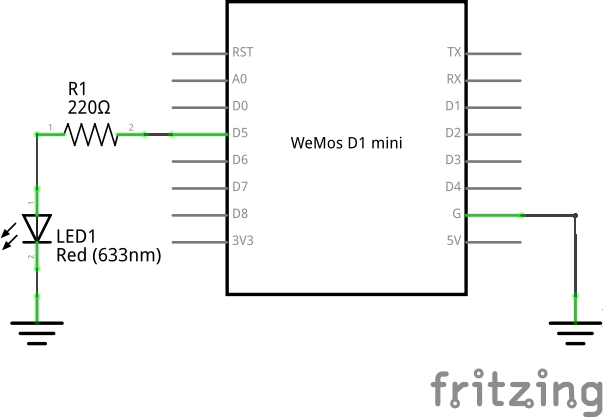
The resistor is symbolized by a zig-zag. The LED is marked by a diode symbol (a triangle with a bar), with additional two arrows showing that it’s a light emitting diode. The board itself doesn’t have a special symbol – instead it’s symbolized by a rectangle with the board’s name written in it.
There is also a symbol for “ground” – the three horizontal lines. Since a lot of components need to be usually connected to the ground, instead of drawing all those wires, it’s easier to simply use that symbol.
Here are some more symbols:

It’s important to learn to read and draw electric schematics, because anything more advanced is going to use them, and you will also need them when asking for help on the Internet.
Analog to Digital Converter
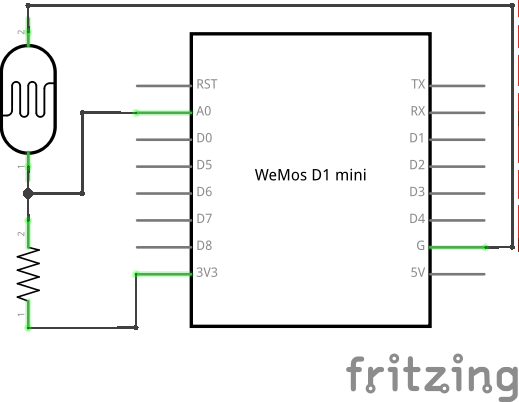
Our board has only one “analog” pin, A0 . That pin is connected to an ADC, or “analog to digital converter” – basically an electronic voltmeter, which can tell you what voltage is on the pin. The one we have can only measure from 0 to 1V, and would be damaged if it got more than 1V, so we have to be careful.
We will connect a photo-resistor to it. It’s a special kind of a resistor that changes its resistance depending on how much light shines on it. But to make this work, we will need a second, fixed, resistor to make a “volatge divider”. This way the voltage will change depending on the resistance of our photo-resistor.
Now, we will just read the values in our program, and print them in a loop:
from machine import ADC adc = ADC(0) while True: print(adc.read())
You should see a column of numbers changing depending on how much light the photo-resistor has. Try to cover it or point it toward a window or lamp. The values are from 0 for 0V, to 1024 for 1V. Ours will be somewhere in between.
Communication Protocols
So far all devices we connected to the board were relatively simple and only required a single pin. More sophisticated devices are controlled with multiple pins, and often have very elaborate ways in which you have to change the pins to make them do something, like sending a character to them, or retrieving a value. Those ways are often standardized, and already implemented for you, so that you don’t have to care about all the gory details – you just call high-level commands, and the libraries and/or hardware in your board handles it all for you.
Among the most popular protocols are UART, I²C and SPI. We are going to have examples of each of them, but we are not going to get into details of how they work internally. It’s enough to know that they let you send bytes to the device, and receive bytes in response.
Neopixels
Those are actually WS2812B addressable RGB LEDs, but they are commonly known as “neopixels”. You can control individually the brightness and color of each of the LEDs in a string (or matrix, or ring). The connection is simple:
![]()
And the code for driving them is not very complex either, because the library for generating the signal is included in Micropython:
from machine import Pin import neopixel pixels = neopixel.NeoPixel(Pin(14, Pin.OUT), 8) pixels[0] = (0xff, 0x00, 0x00) pixels.write()
Where 8 is the number of LEDs in a chain. You can create all sorts of animations, rainbows and pretty effects with those.
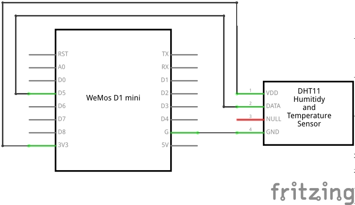
Temperature and Humidity
The DHT11 and DHT22 sensors are quite popular for all sorts of weather stations. They use a single-wire protocol for communication. MicroPython on ESP8266 has that covered:
from machine import Pin import dht sensor = dht.DHT11(Pin(14)) sensor.measure() print(sensor.temperature()) print(sensor.humidity())
The connections are simple:
LED Matrix and 7-segment Displays
Adafruit sells a lot of “backpacks” with 7- or 14-segment displays or LED matrices, that we can control easily over I²C. They use a HT16K33 chip, so that we don’t have to switch on and off the individual LEDs – we just tell the chip what to do, and it takes care of the rest.
The schematic for connecting any I²C device will be almost always the same:
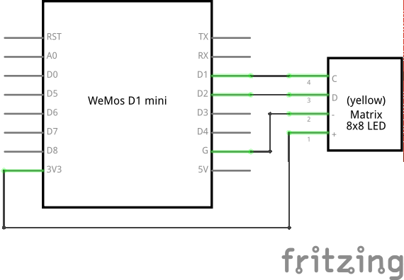
The two resistors on the schematic are needed for the protocol to work reliably with longer wires. For our experiments, it’s enough to rely on the pull-up resistors that are built into the board we are using.
The communication with the backpack is relatively simple, but I wrote two libraries for making it more convenient. For the matrix:
from machine import I2C, Pin from ht16k33_matrix import Matrix8x8 i2c = I2C(sda=Pin(4), scl=Pin(5)) display = Matrix8x8(i2c) display.brightness(8) display.blink_rate(2) display.fill(True) display.pixel(0, 0, False) display.pixel(7, 0, False) display.pixel(0, 7, False) display.pixel(7, 7, False) display.show()
and for the 7- and 14-segment displays:
from machine import I2C, Pin from ht16k33_seg import Seg7x4 i2c = I2C(sda=Pin(4), scl=Pin(5)) display = Seg7x4(i2c) display.push("8.0:0.8") display.show()
TFT LCD Display
The I²C protocol is nice and simple, but not very fast, so it’s only good when you have a few pixels to switch. With larger displays, it’s much better to use SPI, which can be much faster.
Here is an example on how to connect an ILI9340 display:
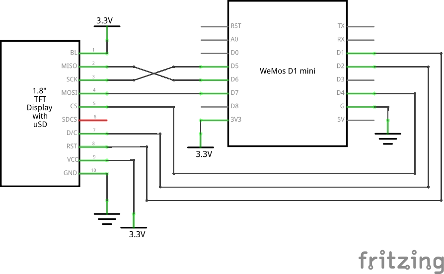
And here is a simple library that lets you draw on that display:
from machine import Pin, SPI import ili9341 spi = SPI(miso=Pin(12), mosi=Pin(13), sck=Pin(14)) display = ili9341.ILI9341(spi, cs=Pin(2), dc=Pin(4), rst=Pin(5)) display.fill(ili9341.color565(0xff, 0x11, 0x22)) display.pixel(120, 160, 0)
As you can see, the display is still quite slow – there are a lot of bytes to send, and we are using software SPI implementation here. The speed will greatly improve when Micropython adds hardware SPI support.
© Copyright 2016, Radomir Dopieralski Revision 4a04e59498a0 .
Versions latest Downloads pdf html epub On Read the Docs Project Home Builds Free document hosting provided by Read the Docs.