Использование GPIO из Python на Raspberry Pi
Делюсь своим опытом, полученным при изучении задачи вынесенной в заголовок. В статье рассматриваются два варианта работы, которые можно использовать в Python-программах, обращающихся к портами GPIO Raspberry Pi.
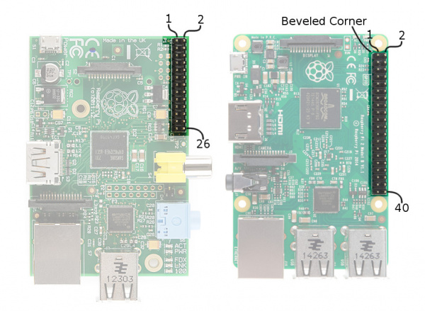
Порты GPIO Raspberry Pi выглядят следующим образом:
Одним из вариантов работы с GPIO является интерфейс Sysfs. Подробнее о Sysfs интерфейсе GPIO здесь. В этом случае для обращения к портам GPIO используются операции чтения и записи файлов. Для использования конкретного вывода его нужно зарезервировать и установить направление на вход или на выход. После окончания работы с портом его нужно освободить, чтобы другие процессы могли его использовать.
Резервирование порта (XX — номер нужного порта):
$ echo XX > /sys/class/gpio/export При успешном резервировании появляется новая папка по адресу /sys/class/gpio/gpioXX/ . Установка направления выполняется так:
$ echo "out" > /sys/class/gpio/gpioXX/direction $ echo "in" > /sys/class/gpio/gpioXX/direction Установка высокого и низкого уровней для порта, настроенного на выход выполняется так:
$ echo 1 > /sys/class/gpio/gpioXX/value $ echo 0 > /sys/class/gpio/gpioXX/value Определение состояние порта, настроенного на вход делается так:
$ cat /sys/class/gpio/gpioXX/value Освобождение порта после окончания его использования:
$ echo XX > /sys/class/gpio/unexport Для упрощения работы с GPIO через интерфейс Sysfs мне встретились две утилиты. Одна из них WiringPi GPIO utility, другая quick2wire-gpio-admin.
Основная задача, решаемая этими утилитами — это предоставление возможности работы с GPIO от имени непривилегированного пользователя. При этом WiringPi GPIO utility более функциональна.
Я для работы с GPIO остановился на пакете RPIO (на момент написания последней была версия 0.10.0). Этот пакет работает с портами GPIO напрямую, обращаясь к регистрам BCM2708 через специальное устройство /dev/mem . Что такое RPIO:
Advanced GPIO for the Raspberry Pi. Extends RPi.GPIO with PWM, GPIO interrups, TCP socket interrupts, command line tools and more
RPIO позиционируется как улучшенный и расширенный вариант другого модуля, RPi.GPIO. В документации непосредственно на RPIO подробно рассмотрены только возможности, отсутствующие в RPi.GPIO, по этому за описанием общих для этих модулей функций нужно обращаться к документации RPi.GPIO, доступной здесь.
Устанавливается пакет следующей командой:
Кроме python-модулей устанавливаюся две программы: rpio-curses и rpio. С их помощью можно, например, получить текущий режим и состояние GPIO и, при желании, изменить их. Так выглядит работа с rpio-curses:

Так можно получить информацию о системе:
$ rpio --sysinfo 000f: Model B, Revision 2.0, RAM: 512 MB, Maker: Qisda Пример python-программы, использующей RPIO:
import RPIO import time NRF_CE = 24 # set up output channel with an initial state RPIO.setup(NRF_CE, RPIO.OUT, initial=RPIO.LOW) for i in range(10): RPIO.output(NRF_CE, 1) time.sleep(1) RPIO.output(NRF_CE, 0) time.sleep(1) # reset every channel that has been set up by this program, # and unexport interrupt gpio interfaces RPIO.cleanup() Raspberry gPIo
Relative to its size the Raspberry Pi is a powerhorse of a computer — it can drive HDMI displays, process mouse, keyboard, and camera inputs, connect to the Internet, and run full-featured Linux distributions. But it’s more than just a small computer, it’s a hardware prototyping tool! The Pi has bi-directional I/O pins, which you can use to drive LEDs, spin motors, or read button presses.
This tutorial was written originally for the Raspberry Pi Model B but applies for any Raspberry Pi Models with the standard 2×20 header.
Driving the Raspberry Pi’s I/O lines requires a bit of programming. Programming in what language? Take your pick! A quick glance at the Raspberry Pi GPIO examples shows that there are dozens of programming-language-choices. We’ve pared that list down, and ended up with two really solid, easy tools for driving I/O: Python and C (using the WiringPi library).
If you’ve never driven an LED or read in a button press using the Raspberry Pi, this tutorial should help to get you started. Whether you’re a fan of the easily-readable, interpretive scripting language Python or more of a die-hard C programmer, you’ll find a programming option that suits our needs.
Covered In This Tutorial
In this tutorial we’ll show two different approaches to reading and driving the Raspberry Pi’s GPIO pins: python and C. Here’s a quick overview of what’s covered:
- GPIO Pinout — An overview of the Pi’s GPIO header.
- Python API and Examples
- RPi.GPIO API — An overview of the Python functions you can use to drive GPIO.
- RPi.GPIO Example — An example Python script that shows off both input and output functionality.
- WiringPi Setup and Test — How to install WiringPi and then take it for a test drive on the command line.
- WiringPi API — An overview of the basic functions provided by the WiringPi library.
- WiringPi Example — A simple example program that shows off WiringPi’s input and output capabilities.
Each programming language has it’s share of pros and cons. Python is easy (especially if your a programming novice) and doesn’t require any compilation. C is faster and may be easier for those familiar with the old standby.
What You’ll Need
Here’s a wishlist-full of everything we used for this tutorial.
Some further notes on that bill of materials:
- Your Raspberry Pi should have an SD card with Raspbian installed on it. Check out our How to Install Raspbian tutorial for help with that.
- We’re also assuming you have the necessary mouse, keyboard and display hooked up to your Pi.
- Your Pi will need an Internet connection to download WiringPi. You can use either Ethernet or WiFi (check out our Raspberry Pi WiFi tutorial for help with that.
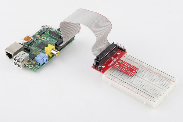
- The Pi Wedge isn’t quite required, but it does make life a lot easier. If you want to skip the breakout, you can instead use Male-to-Female jumpers to connect from Pi to breadboard.
- Of course, feel free to swap in your preferred button and LEDs.
Suggested Reading
This tutorial will assume you have Raspbian installed on your Raspberry Pi. Raspbian is the most popular, well-supported Linux distribution available for the Pi. If you don’t have Raspbian set up, check out our Setting Up Raspbian tutorial before continuing down this rabbit hole.
Other, more general purpose tutorials you might be interested in reading include:
- Pulse-Width Modulation — You can use PWM to dim LEDs or send signals to servo motors. The RPi has a single PWM-capable pin.
- Light-Emitting Diodes (LEDs) — To test the output capabilities of the Pi, we’ll be driving a lot of LEDs.
- Switch Basics — And to test inputs to the Pi, we’ll be using buttons and switches.
- Pull-Up Resistors — The Pi has internal pull-up (and pull-down) resistors. These are very handy when you’re interfacing buttons with the little computer.
Suggested Viewing
Check out our Raspberry Pi video tutorials if you want a more visual introduction to the Pi!
GPIO Pinout
The Raspberry Pi offers up its GPIO over a standard male header on the board. Over the years the header has expanded from 26 pins to 40 pins while maintaining the original pinout.

If you’re coming to the Raspberry Pi as an Arduino user, you’re probably used to referencing pins with a single, unique number. Programming the Pi’s hardware works much the same, each pin has its own number. and then some.
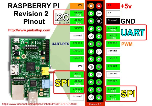
There are (at least) two, different numbering schemes you may encounter when referencing Pi pin numbers: (1) Broadcom chip-specific pin numbers and (2) P1 physical pin numbers. You’re usually free to use either number-system, but many programs require that you declare which scheme you’re using at the very beginning of your program.
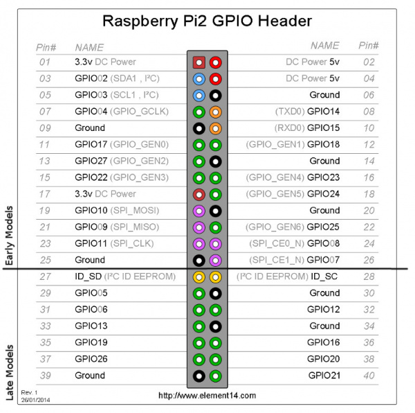
Here’s a table showing all 26 pins on the P1 header, including any special function they may have, and their dual numbers:
Wedge Silk Python (BCM) WiringPi GPIO Name P1 Pin Number Name WiringPi GPIO Python (BCM) Wedge Silk 3.3v DC Power 1 2 5v DC Power SDA 8 GPIO02 (SDA1, I2C) 3 4 5v DC Power SCL 9 GPIO03 (SCL1, I2C) 5 6 Ground G4 4 7 GPIO04 (GPIO_GCLK) 7 8 GPIO14 (TXD0) 15 TXO Ground 9 10 GPIO15 (RXD0) 16 RXI G17 17 0 GPIO17 (GPIO_GEN0) 11 12 GPIO18 (GPIO_GEN1) 1 18 G18 G27 27 2 GPIO27 (GPIO_GEN2) 13 14 Ground G22 22 3 GPIO22 (GPIO_GEN3) 15 16 GPIO23 (GPIO_GEN4) 4 23 G23 3.3v DC Power 17 18 GPIO24 (GPIO_GEN5) 5 24 G24 MOSI 12 GPIO10 (SPI_MOSI) 19 20 Ground MISO 13 GPIO09 (SPI_MISO) 21 22 GPIO25 (GPIO_GEN6) 6 25 G25 CLK (no worky 14) GPIO11 (SPI_CLK) 23 24 GPIO08 (SPI_CE0_N) 10 CD0 Ground 25 26 GPIO07 (SPI_CE1_N) 11 CE1 IDSD 30 ID_SD (I2C ID EEPROM) 27 28 ID_SC (I2C ID EEPROM) 31 IDSC G05 5 21 GPIO05 29 30 Ground G6 6 22 GPIO06 31 32 GPIO12 26 12 G12 G13 13 23 GPIO13 33 34 Ground G19 19 24 GPIO19 35 36 GPIO16 27 16 G16 G26 26 25 GPIO26 37 38 GPIO20 28 20 G20 Ground 39 40 GPIO21 29 21 G21 This table shows the Pi pin header numbers, element14 given names, wiringPi numbers, Python numbers, and related silkscreen on the wedge.
Note: The Broadcom pin numbers above relate to Pi Model 2 and later only. If you have an older Rev1 Pi, check out this link for your Broadcom pin numbers.
As you can see, the Pi not only gives you access to the bi-directional I/O pins, but also Serial (UART), I 2 C, SPI, and even some PWM («analog output»).
Hardware Setup
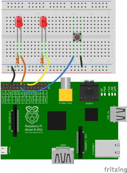
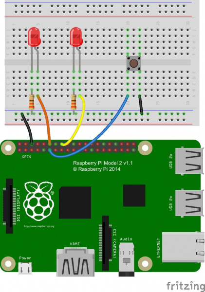
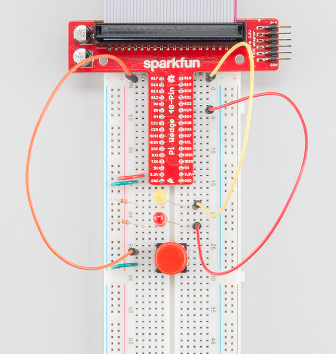
To get a head start you can assemble the circuit now. We’ll use this setup for both the C and Python examples. We’ll use two LEDs to test the output functionality (digital and PWM), and a button to test the input.
Our two LEDs are connected to the Pi’s GPIO 18 and GPIO 23 — those are the Broadcom chip-specific numbers. If you’re basing your wiring off the P1 connector pin numbers, that’d be pins 12 and 16.
The button is connected to Broadcom GPIO 17, aka P1 pin 11.
If you have Pi Wedge, the hookup should be pretty straight-forward. It’ll look a little something like this when you’re done:
If you don’t have a Pi Wedge, male-to-female jumper wires help to make an easy transition from Pi to breadboard.
Jumper Wires Premium 6″ M/F Pack of 10
This is a SparkFun exclusive! These are 155mm long, 26 AWG jumper wires terminated as male to female. Use these to jumper fro…