- Saved searches
- Use saved searches to filter your results more quickly
- License
- sgjava/nodemcu-lolin
- Name already in use
- Sign In Required
- Launching GitHub Desktop
- Launching GitHub Desktop
- Launching Xcode
- Launching Visual Studio Code
- Latest commit
- Git stats
- Files
- README.md
- About
- How to Setup the ESP8266 Arduino IDE with the NodeMCU V3 (ESP8266 ESP12e)
- Starting the nodeMCU
- ESP8266 Arduino Tutorial
- Install USB To Serial Drivers
- External Power Source
- ESP8266 Arduino IDE Boards Manager
- Now Install the nodeMCU Boards
- ESP8266 Arduino Example Sketch
- ESP8266 Arduino Example Output
Saved searches
Use saved searches to filter your results more quickly
You signed in with another tab or window. Reload to refresh your session. You signed out in another tab or window. Reload to refresh your session. You switched accounts on another tab or window. Reload to refresh your session.
Run NodeMCU on ESP8266 LoLin V3
License
sgjava/nodemcu-lolin
This commit does not belong to any branch on this repository, and may belong to a fork outside of the repository.
Name already in use
A tag already exists with the provided branch name. Many Git commands accept both tag and branch names, so creating this branch may cause unexpected behavior. Are you sure you want to create this branch?
Sign In Required
Please sign in to use Codespaces.
Launching GitHub Desktop
If nothing happens, download GitHub Desktop and try again.
Launching GitHub Desktop
If nothing happens, download GitHub Desktop and try again.
Launching Xcode
If nothing happens, download Xcode and try again.
Launching Visual Studio Code
Your codespace will open once ready.
There was a problem preparing your codespace, please try again.
Latest commit
Git stats
Files
Failed to load latest commit information.
README.md

These are my notes for flashing and programming the LoLin V3 ESP8266 ESP-12E CH340G WIFI Network Development Board. This may work on other ESP8266 based boards as well. This is for Linux only and specifically on Ubuntu 18.04 x84-64. I suspect it will work on other Linux distributions.
I bought 5 on ebay with shipping they were about $3.59 US each. They come from China at that price, so you are going to wait a few weeks to reach the US. Search EBay for «NodeMcu Lua ESP8266 ESP-12E» The LoLin ones I bought came with 4 MB flash. This particular board is too wide for a standard breadboard, but you can attach 2 mini breadboards together.
You want to make sure Ubuntu discovers your device. I just plugged it in without any additional drivers and it showed up. I used a standard micro USB cable to connect to PC.
- lsusb
- Bus 006 Device 002: ID 1a86:7523 QinHeng Electronics HL-340 USB-Serial adapter
- Device should show up as serial port /dev/ttyUSB0 if something doesn’t already occupy that port.
This will bring your device up to the latest NodeMCU release. I used the dev branch with floating point. I had to use master branch to get u8g module working, so build to suite your needs.
- Use NodeMCU custom builds to create a NodeMCU image.
- I selected dev branch and used pre-selected defaults.
- sudo usermod -a -G dialout username (Use a non-root username)
- You will have to log out or reboot for this to take effect.
- sudo -H pip install esptool
- esptool.py chip_id
Connecting. Detecting chip type. ESP8266 Chip is ESP8266EX Features: WiFi Uploading stub. Running stub. Stub running. Chip ID: 0x00000000 Hard resetting via RTS pin.
- esptool.py flash_id
- Detected flash size: 4MB
- esptool.py erase_flash
- esptool.py write_flash —flash_mode dio 0x00000 nodemcu-dev-7-modules-2018-03-10-17-09-58-float.bin
Stuck in boot loop or unable to flash
I had an instance where my code was supposed to put the NodeMCU in deep sleep, but crashed instead. Since I used a init.lua I was unable to flash, erase flash, etc. A lot of the solutions you’ll find out there do not work. The only thing that worked for me was to:
- Run wire from RST to GND
- Plug in NodeMCU to computer
- Remove wire from GND
- Flash or erase as normal
I’m using ESPlorer, but Arduino IDE could probably be used as well.
- Install Java 8 JDK if you do not have Java installed.
- Download latest ESPlorer.zip
- Extract to ~/
- Run ESPlorer
- cd ~/ESPlorer
- java -jar «ESPlorer.jar»
- NodeMCU dev branch uses 115200 baud, not 9600. It should auto detect the port.
- Click on Open, click RTS twice and device should auto detect
Communication with MCU..Got answer! Communication with MCU established. AutoDetect firmware. Can't autodetect firmware, because proper answer not received (may be unknown firmware). Please, reset module or continue. NodeMCU custom build by frightanic.com branch: dev commit: 5c8af3c452574448d471e271231b36ac3fff6b1b SSL: false modules: file,gpio,net,node,tmr,uart,wifi build built on: 2018-03-10 17:08 powered by Lua 5.1.4 on SDK 2.1.0(116b762) lua: cannot open init.lua >Let’s try a simple function to list WIFI APs.
function listap(t) -- (SSID : Authmode, RSSI, BSSID, Channel) print("\n"..string.format("%32s","SSID").."\tBSSID\t\t\t\t RSSI\t\tAUTHMODE\tCHANNEL") for ssid,v in pairs(t) do local authmode, rssi, bssid, channel = string.match(v, "([^,]+),([^,]+),([^,]+),([^,]+)") print(string.format("%32s",ssid).."\t"..bssid.."\t "..rssi.."\t\t"..authmode.."\t\t\t"..channel) end end- Select all the code in the editor.
- Click Block button and code should upload to ESP.
- Clear editor and paste wifi.sta.getap(listap)
- Put cursor on line and click Line button
> wifi.sta.getap(listap) > SSID BSSID RSSI AUTHMODE CHANNEL test e7:98:f1:45:36:b8 -47 3 3 SXE465TF 21:e7:1a:88:9b:c5 -65 3 11 xyz1 49:e1:1c:52:65:c6 -64 4 11
This uses a init.lua and blink.lua script to flash an LED on boot. Change pin number in blink.lua as needed. Just create files in ESPlorer (blink.lua first) and click on Run. init.lua sets up wifi to use a static address and runs blink.lua.
About
Run NodeMCU on ESP8266 LoLin V3
How to Setup the ESP8266 Arduino IDE with the NodeMCU V3 (ESP8266 ESP12e)
The easy way to use the ESP8266 is with the Arduino IDE and this ESP8266 Arduino tutorial shows you how to install drivers into the Arduino IDE to program the ESP8266. It then shows you an example sketch using wifi.
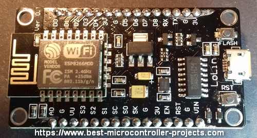
The Lolin nodeMCU V3 breakout board is an ESP-12E style ESP8266 breakout board which makes it very easy to use an ESP8266 device — you just plug it into a micro USB connector and its ready.
Lolin nodeMCU V3 Board
The board includes its own 3V3 power supply regulator, a reset button, a Flash button and a USB-to-serial chip (CH340G on mine). You can just plug it into a USB port (micro USB connector) and start using it.
When you follow the instructions below, you can program the Lolin NodeMCU as if it were any other Arduino device. This is convenient since it uses the same familiar Arduino IDE programming environment.
Note: Just so you don’t get confused: Lolin is a manufacturer name — I originally thought it meant some kind of extended range radio (similar to a Lora device).
Warning: The Lolin nodeMCU V3 comes with the LUA scripting language flashed into it. Using the ESP8266 Arduino IDE as described below will overwrite the contents of the ESP8266. To get LUA back you can re-flash the firmware. (LUA is interactive scripting language — requiring no compilation, working through a serial interface — but you need to learn another language).
Starting the nodeMCU
When you power up the nodeMCU for the first time you will see this message — when you connect a serial terminal on the PC — such as Tera Term — at 9600, 8 bits, 1 stop bit, no parity (8 1 N):
This is a LUA interface which is an interactive script system — you can type commands directly at the prompt to get the ESP8266 to perform. However the rest of this page shows you how to use the Arduino programming environment to program the board in C/C++ as you would with any other Arduino board.
If you continue past this point and Flash the Arduino sketch then the LUA environment will be overwritten. If you want to use LUA again you will need to re-flash the firmware.
ESP8266 Arduino Tutorial
Install USB To Serial Drivers
The first step in setting up the ESP8266 Arduino IDE is to plug in the NODEMCU and check the Windows device Manager for an entry in the Ports section.
If you don’t see the NodeMCU showing up as shown below then you will need to install drivers. The other possibility is that the NodeMCU is using too much power — I found it would not work from a powered hub but only from direct connection to the PC USB port. It needs 400mA!
External Power Source
Note: You can add an external power source to the Vin connection on the board with voltage >5V. Also connect ground labelled ‘G’ to complete the circuit.
Warning: The AMS1117 absolute maximum input voltage is 15V — do not go above this i.e. do not supply a voltage to ‘Vin’ above 15V.
ESP8266 Arduino IDE Boards Manager
To setup the board use the board manager:
Add the following text to the «Additional Boards Manager URLs»:
Now Install the nodeMCU Boards
Start the Boards manager dialogue. Click Boards Manager.
Search for and install the «esp8266 by ESP8266 community» Entry.
Now select the nodeMCU 1.0 (ESP-12E Module) entry — this is the base type for nodeMCU. nodeMCU is actually the firmware running on an ESP8266 ESP-12E.
Now check that you have similar information to the following — especially these:
- Board «nodeMCU 1.0 (ESP-12E Module)»
- Upload speed «115200baud»
- CPU frequency «80MHz»
- Flash Size «1M (3M SPIFFS)»
Warning: I originally set the Flash Size to 4M no SPIFF — only the WiFi scanner example below worked — The SPIFFS is a virtual file system that allows programs to occupy a space separate to the wifi operational part — its like having a virtual SD card so make sure you use the setting above (or at least allow some SPIFFS room).
ESP8266 Arduino Example Sketch
Use the ESP8266 Arduino IDE to load the following sketch — just copy to white area of the IED and hit the upload button. This shows you a quick example of the ESP8266 Arudino wifi capability.
ESP8266 Arduino Example Output
Here’s the typical output from the sketch using the serial monitor.
Setup done scan start scan done 15 networks found 1: SKY6F103 (-91)* 2: SKY7C621 (-88)* 3: SKY6F103 (-91)* 4: BTWifi-X (-87) 5: BTHub6-2MX3 (-87)* 6: talktalkt8974 (-61)* 7: VM989231-2G (-82)* 8: BNIPOF_6723 (-16)* 9: VM7227168 (-93)* 10: VM0345159 (-92)* 11: BTWifi-with-FON (-88) 12: Virgin Media (-90)* 13: Virgin Media (-93)* 14: VM-guest3451593 (-89)* 15: Virgin Media (-89)*
End of ESP8266 Arduino IDE tutorial showing how to flash an esp8266 with the Arduino IDE making it easy to create C/C++ based programs programmed into the ESP8266.